


Page 40 - IOE_Winter 24
P. 40
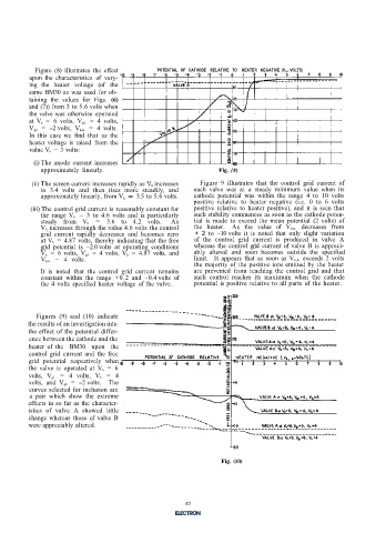
Figure  (8)  illustrates the  effect   POTENTIAL OF CATHODE  RELATIVE  TO  HEATER  NEGATIVE  (V k, h-  VOLTS)
          upon the  characteristics  of  vary-
          ing  the heater  voltage  (of  the
          same  BM30  as was  used  for ob-
          taining the  values  for  Figs.  (6)
          and (7)) from 3 to 5.6 volts when
          the valve was  otherwise  operated
          at  V a  =  6 volts,  V g1  =  4 volts,
          V g2  =  -2 volts,  V k,h-  =  4 volts.
          In this  case  we find  that as  the
          heater voltage  is  raised  from the
          value V h  =  3 volts:
            (i) The anode  current  increases
              approximately linearly.                                 Fig.  (9)
           (ii) The screen current increases rapidly as V h increases   Figure  9  illustrates  that  the control  grid  current  of
              to  3.4  volts  and then  rises  more  steadily,  and   each  valve was  at  a  steady minimum  value  when its
              approximately linearly, from V h  = 3.5 to 5.6 volts.   cathode potential  was within  the  range  4  to  10  volts
                                                              positive  relative  to  heater  negative  (i.e.  0  to  6 volts
           (iii) The control grid current is reasonably constant for   positive  relative  to  heater  positive),  and  it  is seen that
              the  range  V h  = 3  to  4.6  volts  and  is  particularly   such stability commences as soon as the cathode poten-
              steady  from  V h  =  3.6  to  4.2  volts.   As   tial  is  made  to  exceed  the  mean potential  (2  volts) of
              V h  increases through the value 4.6 volts the control   the  heater.  As  the  value  of  V k,h-  decreases from
              grid  current rapidly  decreases  and  becomes  zero   +2 to  -10 volts  it  is  noted  that  only slight  variation
              at V h  =  4.87  volts,  thereby indicating that the free   of  the  control  grid  current  is  produced  in  valve A
              grid  potential  is  -2.0 volts  at  operating  conditions   whereas  the control grid  current of  valve  B is  appreci-
              V a  =  6 volts,  V g1  =  4 volts,  V h  =  4.87  volts,  and   ably  altered  and  soon  becomes  outside the  specified
              V k,h-  =  4 volts.                             limit.  It appears that  as soon  as V k,h-  exceeds  2 volts
                                                              the  majority of  the positive  ions emitted  by  the heater
              It  is  noted  that  the control  grid  current  remains   are prevented  from  reaching  the control grid  and that
              constant  within  the range  +0.2 and  -0.4 volts  of   such  control  reaches  its  maximum  when  the  cathode
              the 4  volts  specified  heater voltage  of  the valve.   potential is positive  relative to all parts  of  the heater.


            Figures  (9)  and  (10)  indicate
          the results of an investigation into
          the effect of the potential differ-
          ence between the cathode and the
          heater of  the  BM30  upon  the
          control grid  current and  the free
          grid  potential  respectively  when
          the valve  is  operated  at V a  = 6
          volts,  V g1  =  4 volts,  V h  = 4
          volts,  and  V g2  =  -2 volts.  The
          curves selected for inclusion are
          a  pair which  show  the  extreme
          effects in so far as the character-
          istics of  valve  A  showed  little
          change whereas  those  of  valve B
          were appreciably altered.


                                                                       Fig. (10)

                                                            7


                                                            40

