


Page 41 - IOE_Winter 24
P. 41
The  curves  of  Fig.  (10)  show  the
           corresponding changes produced in the
           free  grid  potential  of  valves  A  and  B
           as the heater/cathode potential differ-
           ence  is  varied.  The continuous  lines
           denote the  results  obtained at V a  = 6
           volts, V g1  = 4 volts, V h  = 4 volts and
           the  broken  lines show  the  values  at
           V a  = 6 volts,  V g1  = 6 volts and V h  =
           4  volts.  In  all  cases  the  free  grid
           potential is seen to be of constant value
           for  values  of  V k, h-  between  3  and  10
           volts  and  that  as  V k,h-  decreases
           below  2  volts  the  free  grid  potentials
           become  variable and  more  positive.
           Stable operation is seen to occur at the
           recommended  operating condition  of
           V k,h-  = 4.
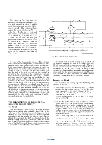
                                                              Fig. (11).  The Balanced Bridge  Circuit.


             A review of the above results indicates (Fig. (6)) that   The  circuit  used is  shown  in  Fig.  (11)  in  which  all
           variation of  anode voltage alone, within the range con-   the required  voltages  are  seen  to  be supplied  by  one
           sidered, causes little change in the control grid current.   12-volt battery  (B) via  a resistance network.  The pro-
           Such does not apply, however, in the case of  variations   cedure for  stabilising  the circuit  is  to  adjust  the four
           of  the  screen and heater voltages either of  which, as is   resistances  R 2, R 3,  R a  and  R n  ohms,  in  terms  of  the
           shown  in Figs.  (7)  and (8),  can drive the control grid   operating conditions and corresponding valve character-
           into the state of  free grid  potential  and then produce a   istics, such that  the galvanometer current  shall be zero
           reversal  in  the direction  of  the control  grid  current.   and  constant  for  small variations  in  heater current
           Figs.  (9) and  (IO)  show how  the value of  V k, h- can be   caused by varying either R 4  or the battery voltage.
           used  as a  means  of  controlling and  stabilising the con-
           trol grid  current.   The  vital  effect  of  the  free  grid
           potential  of  the  valve,  upon  the  characteristics of  the   Balancing  the  Circuit
           valve,  is  also  noted  and it  is  seen  that  the  excessive   The  procedure for  setting  up  and  balancing  the
           reverse control grid current produced when  the control   circuit is as follows:
           grid  is  operated  at  a  potential more  positive  than  the
           appropriate  free  grid  potential  renders  the  valve  un-   1. Measure the values of  the heater current (I h). anode
           serviceable as an electrometer valve, i.e. for electrometer   current (I a)  and  screen  current (I g1)  for the  valve
           operation the control grid  potential of  the valve, at the   when  operated  at  its rated  voltages  of  V a  =  6
           working point, must be more negative than the free grid   volts,  V g1  =  4  volts,  V g2  =  -2 volts,  V h  =  4
           potential  of  the valve under  such conditions of  anode,   volts and V k, h-  = 4  volts.
           screen,  heater and V k,h-  potentials.                [Let the measured values be I h =  .125 amp., I a  =  116  µA
                                                                  and I gl  = 200 µA].

           THE  PERFORMANCE  OF  THE  BM30  IN  A               2. Set  up the  heater circuit  with  a  suitable centre-
           BALANCED BRIDGE CIRCUIT                                tapped resistor  R 1,  of  approximately  10,000  ohms,
                                                                  shunted  across  the  heater  terminals and  to  be  in
           The  Circuit                                           series with  R 3, R 4  and  the 12-volt  storage battery.
             The sensitivity of  a  direct-current  amplifier using an   Select  R 3  and  R 4  such  that R 4  may  be  adjusted  to
                                                                  produce a steady heater voltage of  4 volts and may
           electrometer valve is often limited by the stability of  the   also  be  used  to  produce  the required  variations  of
           valve and of  the batteries which supply its power. Valve   the heater current.
           stability had  been carefully considered in the design and
           construction  of  the  BM30  and  circuit  conditions to   [If  I h  =  0.125  amp. and  V 2  =  8 volts  the  value  of  R 3
                                                                                             8
           effectively counteract  the drift  and  fluctuations of  the   for  balance  will  be  =  -  =  -  =  64  ohms.  The
                                                                                       V 2
           battery supply  were now  considered-with  the  result                          0.125
           that  it  was  decided  to  modify the Barth-Penick exten-   value  of  R 4  will  then be such  as will  drop  the  voltage by
                                                                                        I h
           sion of the DuBridge and Brown circuit so as to render   which  the battery  p.d.  exceeds  12 volts  and  capable  of
           it applicable to the indirectly heated BM30.           producing the requisite values of heater current variation].
                                                            8


                                                            41

