


Page 36 - IOE_Winter 24
P. 36
of illumination.  To meet this need  the Ferranti Valve   the baking and processing schedules. The glass envelope
          Development  Laboratories produced  a  range  of  single   is  silicone coated  to  render  it  moisture  repellent  and
          tetrode and  double  tetrode  indirectly heated  electro-   carries internal  and  external guard  rings  R 1  and  R 2
          meter valves, employing oxide-coated cathodes.  These   respectively.  The  internal guard  ring,  on  which  part
          valves  were  of  normal radio  valve dimensions and  the   of  the barium  getter  film  is deposited, is connected  to
          aim  eventually became  that  of  producing similar  type   the anode via the spring contact S.  The external guard
          electrometer  valves  of  smaller dimensions  and,  if   ring is  connected  to  the anode  pin  of  the base via  the
          possible, more rigid construction.                   nickel gauze ring N.
            Directly heated subminiature electrometer valves had   In  assembling  the  valve  particular  attention  is  paid
          already been produced by  home and overseas manufac-   to ensuring that
          turers  but,  in  many  cases, they  did not  incorporate   (i)  The  control  grid  is mounted  (via  its insulators)
          guard rings and the valves were far more unstable than     rigidly relative to the anode,
          their predecessors.  Such valves, it is true, satisfied the
          immediate need for a means of  detecting radiation, and   (ii)  The micas hold  the screen and the cathode rigid
          for  short-term  measurement, but  many  of  them  were    relative to the anode.
          relatively useless  for quantitative, long-term,  or repeti-   The  cathode  is  rigidly connected  to  the bottom  mica
          tional  measurements-due  to their  excessive  sporadic   and  is  able to  expand through the  central  hole in  the
          drift  of  characteristics.  In  consequence  our  desire   top  mica.  The  screen  support  wires  are  rigidly  con-
          became that of  miniaturising the indirectly heated valve   nected  by  a  nickel bridge  and one of  them  is welded
          whilst  retaining,  unless  able  to  improve upon,  our   to  base pin  6.  The  bottom  mica  is  picot-edged and
          existing  methods  of  obtaining  high stability-and  the   grips the  internal  surface of  the  glass envelope.
          outcome has  been  the development, on a B7G base, of
          the  indirectly  heated  single  tetrode electrometer  valve   The order of  location of  the electrodes (starting from
          type BM30.                                           the  centre)  is  heater, cathode,  screen  (or accelerator)
                                                               grid, control grid and anode.  The guard rings are both
          DESIGN                                               connected to the anode.
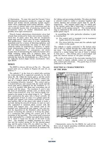
            The BM30 is shown, full size, in Fig. (2).   The com-   ELECTRICAL CHARACTERISTICS
          ponent  parts  are,  as  shown  in Figures  (1)  and  (3),  as   OF THE  BM30
          follows:-
            The cathode C, in the form of  a nickel tube carrying
          the oxide-coating 0, is  supported coaxially by  the disc
          micas  M 1,  M 2  within  the screen grid g 1  and the anode
          A of  the  valve and  surrounds  the heater h which  con-
          sists of  a  v-shaped  spiral of  tungsten wire coated  with

          an  insulating refractory  material.  The control  grid  g 2
          is located between, and coaxial with, the anode and the
          screen  grid  and  is  supported  (by  the insulators  I 1,  I 2)
          so  as  to  be  parallel  with them  and  everywhere out  of
          contact with  the micas.  The  insulators  I 1  and  I 2  take
          the  form of  metal/glass  tubular  seals, as shown  more
          clearly in the section of I 1  (Fig. (l)), and are rigidly con-
          nected to the anode by the metal straps S 1, S 2.  During
          their  construction the  glass  tube  is  fused  centrally,  by
          the application of  heat, to cause it to collapse upon the
          straight grid  support  wire (whose coefficient of  expan-
          sion  matches  that  of  the  glass) with  which  it forms  a
          seal and, during the process of  fusion, its ends are suit-
          ably  supported to  maintain  them  coaxial  with  the
          control grid  support  wire.  The  tubular  ends  of  the
          insulator now  enshroud the grid  support wire and pre-
          vent  the deposition on  the  insulator, either  during  the
          process  of  flashing  the cathode  or of  firing the getter,
          of  a  conducting  film  joining  the control  grid  to the
          remainder of  the assembly.  The control grid connection
          is also surrounded by a similar type glass-sleeve insula-
          tor  I,  which  is fused  into the  top  of  the  bulb  of  the
          valve.  The  assembly  is  suitably mounted  on  a  B7G                   Fig.  (4)
          base  and  the contact  spring (S)  for the internal guard
          ring,  and  the getter frame (F), are added  (see Fig..  1)   Characteristic curves for the BM30, for each of  the
          before it is  sealed  into the cylindrical glass bulb (Fig.   three sets of  typical operating conditions specified, are
          3)  which  is then evacuated and stored in readiness for   shown in Figs. (4) and (5).


                                                            3


                                                            36

