


Page 39 - IOE_Winter 24
P. 39
sidered.  A selection of  the results obtained is shown in
           Figures (6) to (10).


                                Fig.  (6)

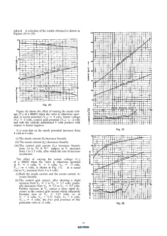
             Figure (6) shows the effect of varying the anode volt-
           age (V a) of  a BM30 when  the valve is  otherwise oper-
           ated at screen potential (V g1)  = 4 volts, heater voltage
           (V h)  = 4 volts, control grid potential (V g2)  = -2 volts
           and  with  the cathode maintained  4  volts  positive with
           respect to heater negative.
             It is  seen that  as the anode  potential  increases from              Fig.  (7)
           4 volts to 6 volts:

            (i) The anode current (I a) increases linearly.
            (ii) The screen current (I g1) decreases linearly.
           (iii) The  control  grid  current  (I g2)  increases linearly
               from  1.6 to  3.0  X  10 -15   ampere as  V,  increases
               from 4 to 5.5 volts, after which the rate of  increase
               accelerates.
             The  effect  of  varying  the  screen  voltage  (V g1)
           of  a  BM30  when  the  valve is  otherwise operated
           at  V a  =  6  volts,  V h  =  4  volts,  V g2  =  -2 volts,
           V k, h- =  4  volts,  is  shown  in  Fig.  (7).   It  is  noted
           that as V g1  increases from 3 to 6 volts:
            (i) Both the  anode current and the screen current in-
               crease linearly.
            (ii) The  control  grid  current, after  showing  a  slight
               increase from V g1  = 3 to V g1  = 3.5 volts, gradu-
               ally decreases from V g1  = 3.5 to V g1  = 4.5 volts.
               Further  increase  in  V g1  causes  a  more rapid de-
               crease in the control grid current which  ultimately
               becomes  zero  at  V g1  =  5.25  volts, i.e.  at
               V a  = 6  volts,  V g1  =  5.25  Volts, V h  = 4  volts,
               Vk, h- =  4  volts,  the  free  grid  potential  of  this
               particular valve is -2 volts.                                        Fig.  (8)


                                                            6


                                                            39

