


Page 42 - IOE_Winter 24
P. 42
3. Join the  cathode to  the  positive  terminal  of  the
              heater.  The control grid voltage, obtained from the
              centre-tap  of  the heater shunt  resistor R 1, will  now
              be  at  the  specified  value  of  2  volts  negative  with
              respect to the cathode.
            4. Into  the  screen  circuit introduce  the  resistor R d  of
              such  value  as to  produce,  when  conducting  the
              screen current I g1  amp., a voltage drop V 1  equal to
              the  difference between  the  specified  operating volt-
              ages of  the anode and of  the screen.
                                                    6- 4
                                         V a-V g1
                 [If  I g1  =  200µA  then  R d  =   =
                                          I g1    200  x  10 -6
                                  =  1O,OOO  ohms].
            5.  Introduce the resistor R n  into the screen circuit and
              let it be  of  such value as to produce a volt drop of
              (V 2  -V 1) when conducting the current I g1  amp.
                                  8 - 6
                 [R n  =   V 2 - V 1   =   =  10,000  ohms].
                         I g1    200x10 -6
            6. Set  the  anode  supply  voltage  V a(b)  to  an arbitrary
              value  between V 2  and V 1  and  such  that  the anode
              potential V a  will be 6 volts.
                         [Let V ( )  = 7.02 volts].
                              a b
            7. Select resistor  R a  to have  value  such  that  (V a(b)
             - R a.I a)  =  (V 2  ----      .I gl).
                              R n
                                            7.02 -  8  + 2
                        V a(b)  - V 2  +  Rn.I gl   =
               [i.e. R a  =
                                I a           116  X  10 -6
                              = 8,793  ohms].
            8. Close the galvanometer circuit and, if  current flows,
             adjust R a  to  reduce  the galvanometer  current  to
              zero.
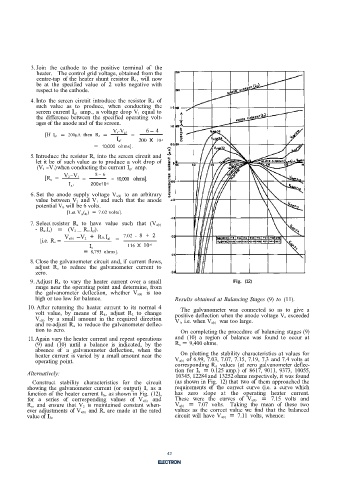
            9. Adjust R 4  to vary  the  heater current  over  a  small            Fig.  (12)
             range near the operating point  and determine, from
             the  galvanometer  deflection,  whether V a(b)  is  too
             high or too low for balance.                     Results obtained at Balancing Stages (9)  to (11).
           10. After  returning  the heater  current  to  its  normal  4   The  galvanometer  was  connected  so  as  to  give  a
             volt  value,  by  means  of  R 4,  adjust  R 2  to change   positive deflection when the anode voltage V a  exceeded
             V a(b)  by  a  small amount  in  the  required direction   V 1, i.e. when V a(b)  was too large.
             and  re-adjust R a  to reduce the galvanometer deflec-
             tion to zero.                                      On completing the procedure of  balancing stages (9)
           11. Again vary the heater current and repeat operations   and  (10)  a  region  of  balance  was  found to  occur  at
             (9)  and  (10)  until  a  balance  is  indicated,  by  the   R a  = 9,400 ohms.
             absence  of  a  galvanometer  deflection,  when  the
             heater current  is varied by a small amount near the   On plotting the  stability characteristics at values for
             operating point.                                 V a(b)  of 6.99, 7.03, 7.07, 7.15, 7.19, 7.3  and 7.4 volts at
                                                              corresponding R a  values  (at  zero galvanometer deflec-
           Alternatively:                                      tion  for I h  = 0.125 amp.) of  8617, 9011,  9373,  10055,
                                                               10345, 12284 and 13252 ohms respectively, it was found
            Construct stability  characteristics  for  the circuit   (as shown in Fig.  12) that two of  them approached the
           showing  the  galvanometer current  (or  output)  I o  as a   requirements  of  the  correct curve  (i.e.  a  curve  which
           function of  the heater current I h, as shown in Fig. (12),   has zero  slope  at  the operating  heater  current.
           for  a  series  of  corresponding  values  of  V a(b)  and   These  were  the curves  of  V a(b)  =  7.15  volts  and
           R a, and  ensure  that  V 2  is  maintained  constant when-   V a(b)  =  7.07  volts.  Taking the  mean  of  these  two
           ever  adjustments  of  V a(b)  and  R a  are made  at the rated   values  as  the  correct value  we  find  that  the  balanced
          value of  I h.                                      circuit will  have V a(b)  = 7.11  volts, whence:

                                                            9


                                                            42

