


Page 37 - IOE_Winter 24
P. 37
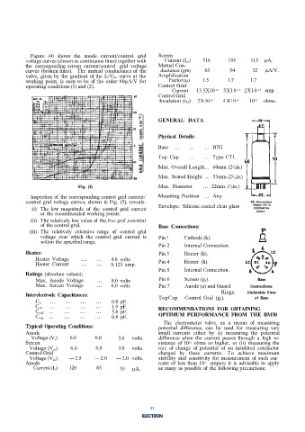
Figure  (4)  shows  the anode-  current/control  grid   Screen
           voltage curves (shown as continuous lines) together with   Current (I g1)   316   185   115  µA.
           the  corresponding screen  current/control  grid  voltage   Mutual Con-
           curves (broken lines).  The mutual conductance of  the   ductance (gm)   65     54       32   µA/V.
           valve, given  by  the gradient  of  the Ia/Vg 2  curve at the   Amplification
           working  point,  is  seen  to be  of  the order  60µA/V for   Factor  (µ)   1.5   1.7   1.7
           operating conditions (1) and (2).                   Control Grid
                                                                    Current   13.5X10 -15   5X10 -15   2X10 -15   amp.
                                                               Control Grid
                                                               Insulation (rg 2)  2X l0 14   4 X lO 14   10 15   ohms.


                                                               GENERAL  DATA


                                                               Physical  Details:

                                                               Base  ...   ...   ...  B7G
                                                               Top Cap     ...   ...  Type CT1

                                                               Max. Overall Length.. .  60mm. (2 / 8in.)
                                                                                            3
                                                               Max. Seated Height  ...  53mm. (2 / 16in.)
                                                                                            1
                                                                                          7
                                Fig.  (5)                      Max. Diameter    ...  22mm. ( / 8in.)
             Inspection of  the corresponding control grid current/   Mounting Position  ...  Any
           control grid  voltage curves, shown in Fig.  (5),  reveals:                             All dimensions
                                                                                                    shown are in
             (i)  The  low  magnitude  of  the control  grid  current   Envelope:  Silicone coated clear glass   millimetres
                                                                                                     (max.).
                 at the recommended working points.
             (ii)  The relatively low value of  the free grid  potential
                 of  the control grid.                         Base  Connections:
             (iii)  The  relatively extensive  range  of  control  grid
                 voltage  over which  the control  grid  current  is   Pin 1   Cathode (k).
                 within the specified range.
                                                               Pin 2     Internal Connection.
           Heater:                                             Pin 3     Heater (h).
               Heater Voltage    ...   ...   4.0  volts        Pin 4     Heater  (h).
               Heater Current    ...   ...   0.125  amp.
                                                               Pin 5     Internal Connection.
           Ratings  (absolute values):
               Max.  Anode Voltage     ...   8.0 volts         Pin 6     Screen (g l).                Base
               Max.  Screen  Voltage   ...   6.0  volts        Pin 7     Anode (a) and Guard       Connections
                                                                                       Rings.
           Interelectrode  Capacitances:                       TopCap    Control Grid  (g 2).     Underside View
                                                                                                    of  Base
                     ...   ...   ...   ...   0.8  pF.
               C in
               C out   . ..   ...   ...   ...   1.9  pF.       RECOMMENDATIONS  FOR  OBTAINING
               C a-g2  ...   ...   ...   ...   5.8  pF.
               C a-g1  ...   ...   ...   ...   0.8  pF.        OPTIMUM  PERFORMANCE FROM  THE  BM30
                                                                 The  electrometer  valve,  as  a  means  of  measuring
           Typical Operating  Conditions:                      potential  difference,  can  be  used  for measuring  very
           Anode                                               small currents  either  by (i)  measuring the  potential
             Voltage (V a)   6.0      6.0      5.0   volts.    difference when  the  current  passes through  a  high  re-
           Screen                                              sistance  of  l0 ohms  or higher,  or (ii)  measuring  the
                                                                           11
            Voltage (V g1)   6.0      4.0      3.0   volts.    rate  of  change  of  potential  of  an  insulated conductor
           Control Grid                                        charged  by  these  currents.  To  achieve maximum
            Voltage (V g2)   -2.5     -2.0    -2.0  volts.     stability  and  sensitivity  for measurement  of  such cur-
           Anode                                               rents of  less  than 10 -9   ampere it  is  advisable to  apply
              Current (I a)   120      85       35   µA.       as many as possible of  the following precautions:

                                                            4


                                                            37

