


Page 34 - Autumn 2024
P. 34
ship to these principles, will help to produce a better  and is automatically transferred to the product register      Doubling
          understanding of the functioning of the machine.      each time the multiplier becomes an odd number.

            Binary notation is the notation of numbers in the
          scale of two, the carry, or point at which the same sym-
          bols are used over again, occurs after the tenth in
          decimals but after the second symbol in Binary.
            If the figures 1 + 1 are added in Binary, it will not
          give the answer 2 as a decimal, but 0 and carry 1, which
          would be written as 10. We thus see that whilst 1
          represents 1, 10 represents 2.
            Similarly, if 10 + 10 are added in Binary, the answer
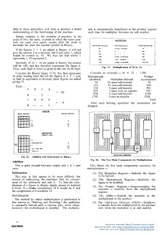
          will be 100, and this therefore represents the figure 4.        Fig. 17. Multiplication of 56 by 23.
          Thus, each digit is twice as great as the one on its right.
            Consider the Binary figure 1111, this then represents  Consider an example:- 56 X 23 = 1288.
          in order reading from the left the figures 8, 4, 2, 1 and,  Multiplicand                      Product                                                                            Fig. 21.  Schematic arrangement of Halving and
                                                                                                                                                                                                      Numerical Example.
          to find its equivalent in decimal, these figures are added  (doubled)  Multiplier (halved)  accumulated
          giving 15.                                                 56       23 since odd transfer        56                         Fig. 19.  Schematic arrangement for Doubling.   must be added into the register position below.  This
                                                                    112       11 since odd transfer       168                                                                        can best be shown by the example:-
                                                                    224        5 since odd transfer       392                      All that is required to double a number is to shift                 50 ÷ 2 = 25.
                                                                    448        2 since even no transfer   392                    it one place to the left, the feed back loops of the
                                                                    896        1 since odd transfer      1288                   multiplicand register are connected so that when doub-  Arrangement of Machine
                                                                   1792        0 zero no transfer       1288                    ling, the "1" feeds back to the "2," the "2" feeds
                                                                                                            Total               back to the "4," the "4" to the "8," and the "8"
                                                                  After each halving operation the remainders arc               to the Carry Memory buss bar.  The 4, 2 and 1 lines
                                                                dropped.                                                        are connected via the half adder to the C.M., since a
                                                                                                                                combination of 4 and any other figure when doubled
                                                                                                                                will require this circuit.
                                                                                                                                  We have chosen the example No. 936 as this entails
                                                                                                                                the use of the Carry Memory.


                                                                                                                                                                                           Fig. 22.  Basic arrangement of Arithmetic Unit.

                                                                                                                                                                                       This shows the five stores, the three registers, the
                                                                                                                                                                                     adder, the complementer and the emitter.  The emitter
                Fig. 16.  Addition and Subtraction in Binary.                                                                                                                        can be used to insert a figure into any of the registers
          Addition                                                Fig. 18.  The Five Main Components for Multiplication.                                                             which would be common to a series of cards.
            This is quite straight forward, simply add 1 to 1 and  This shows the five main components necessary for                                                                   It will be noticed that there are two paths, A and B
          carry.                                                multiplication:-                                                                                                     -thisenables the machine to add together the quanti-
          Subtraction                                               (1) The Multiplier Register-thisholds the figure                  Fig. 20.  Example of Doubling the number 936.  ties held in stores 2, 3, 4 and 5 to store 1, thus enabling
                                                                                                                                                                                     the calculation of the type (A + B) times C to be
            This may at first appear to be more difficult, but          to be halved.                                                                                                carried out as it were in one run.  The stores, with the
          instead of subtracting, the machines find the comple-     (2) The Multiplicand Register-thisholds the                 Halving                                              exception of No. 1, can pass through the complementer.
          ment of the subtractor and add it.  To find the com-          figure to be doubled.
          plement of a figure in Binary simply means to subtract    (3) The Product Register-thisaccumulates the                  To halve the number in the multiplier register each  Shifting Registers
          it from 15-thusthe complement of 6 would be 9 and             amounts it receives from the multiplicand               Binary expressed denomination is shifted one position
                                                                                                                                to the right, but as no decimal digit after halving can
                                                                                                                                                                                       One of the fundamentals of valve registers is that of
          the complement of 4 would be 11.                              register.                                               exceed 9, there will be no carry up the register, and  being able to transfer (or shift) the digit in one position
          Multiplication                                            (4) The Adder-thisadds the amounts in the                   therefore the "ten" detector and rationalising circuits  to the next position, and so on through all the stages of
            The method by which multiplication is performed is          multiplicand to the product.                            are not needed.  One bank of adders is necessary, how-  the register.  The shifting registers are composed of a
          that known as "Halving and Doubling," the multiplier     (5) The Odd-Even Detector (OED)-thisallows                   ever, because when a register position (other than the  series of inter-connected triggers, one series for each
          is repeatedly halved until it reaches zero, while simul-     a transfer from the multiplicand to the product          units position) holds a digit that is an odd number, a 5  register position.
          taneously the multiplicand is doubled.  The multiplic-       only when the multiplier is an odd number.
                                                                                                                                                                                  18
                                                            17


             34
                                                                             Become a member: https://membermojo.co.uk/ie
                                                                     Become a subscriber: https://membermojo.co.uk/subscriber
                                                                         Become a sponsor: https://membermojo.co.uk/sponsor

