


Page 37 - Autumn 2024
P. 37
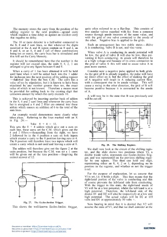
The memory stores the carry from the position of the  quite often referred to as a flip-flop.  This consists of
        adding register to the next position-agrand carry     two similar valves supplied with h.t. from a common
        which requires a time delay as against an incident carry  source through anode resistors of the same value, and
        that requires no delay.                               with the grid of one valve connected to the anode of
          The 10 or more detector is a half-adder connected to  the other.  Negative bias is applied to the grids.
        the 8, 4 and 2 sum lines, so that whenever the digits   Such an arrangement has two stable states-ifvalve
        received at the A and B inputs contain an 8 and 2, an  A is conducting, valve B is not, and vice versa.
        8 and 4, or an 8, 4 and 2 (all of these combinations    When valve A is conducting its anode potential will
        being ten or more), the carry buss bar is stimulated and  be low, the grid of valve B will also be low, thus pre-
        this will set the Carry Memory.                       venting it from conducting; its anode will therefore be
          It should be remembered here that the number in the  at a high voltage and because of its cross connection to
        register will not exceed nine, the units 8, 4, 2, 1 are  the grid of valve A this will tend to cause valve A to
        arranged to give any figure between 0 and 9.         pass more current.
          When a carry of 1 has been obtained it will be held  Consider now a negative pulse applied to both grids.
        until later when it will be added back into the 1 adder  As the grid of B is already negative, the pulse will have
        for inclusion into the next position of the adding register  no direct effect on it, but the effect of making the grid
        -thedotted line from the box C.M.  The carry has a   of A negative will result in A reducing current flow,
        value of ten by stipulation, but it is known to have been  with a consequent rise in its anode voltage.  This will
        stipulated by any number greater than ten, the exact  cause a swing in the other direction, the grid of B will
        value of which is not known.  Therefore a means must  become positive because it is connected to the anode
        be provided for adding back to the existing digit that  of A.
        unknown amount by which the carry exceeds 10.          A will now be in the state that B was previously and
          This is achieved by inserting another bank of adders  will be cut off.
        in the 8, 4 and 2 sum lines and whenever the carry buss
        bar is energised a 4 and 2 filler are entered into these
        adders which causes an addition of 6 to the total of the
        sum lines.
          An example would demonstrate more clearly what
        takes place.  Referring to the lines marked with an X
        in Fig. 26:-
                       Take 8 + 4 = 12.
        This sets the 8 + 4 adders which give out a sum on
        each line, these sums set the C.M. which gives out the
        4 and 2 fillers-thus,reading from the right, we have
        2 followed by in the 4 position a sum on both inputs
        which creates a carry to the 8 position leaving zero at 4.
        The 8 position will therefore have two inputs which will
        create a carry which is not used and leaving a zero at 8.        Fig. 28.  The Shifting Register.
          The adders will therefore give out the figure 2 at the  We shall now look at the circuit of the shifting regis-
        units position, but because the C.M. was set a 1 carry  ter, and the slide shows two positions where VI, a
        will be given out at the tens position-thusgiving the  double triode valve, represents one Eccles-Jordon Trig-
        correct answer of 12.                                ger, and was represented on the previous shifting regis-
                                                             ter by one square.  This then can hold one digit,
                                                             representing either an 8, 4, 2 or 1, depending on its
                                                             position in the register, and whether or not the trigger
                                                             is set.
                                                               For the purpose of explanation, let us assume that
                                                             VI is set, i.e. it holds a digit.  This then means that the
                                                             right-hand portion of the valve is conducting and this
                                                             of course prevents the left-hand side from conducting.
                                                             With the trigger in this state, the right-hand anode of
                                                             VI will be at a low potential, whilst the left hand is at a
                                                             high potential.  Therefore, the left-hand side of the
                                                             diodes D1 and D2 will also be respectively at a low and
                                                             high potential.  The actual values will be D2 at 135
                                                             volts and D1 at approximately 50 volts +.
                  Fig. 27.  The Eccles-Jordon Trigger.         Now bearing in mind that it is desired that V2 will
          This shows the well-known Eccles-Jordon Trigger,   assume the state of V1, and that we shall consider at the

                                                          20


                                                                                                           37
          Become a member: https://membermojo.co.uk/ie
          Become a subscriber: https://membermojo.co.uk/subscriber
          Become a sponsor: https://membermojo.co.uk/sponsor

