


Page 38 - Autumn 2024
P. 38
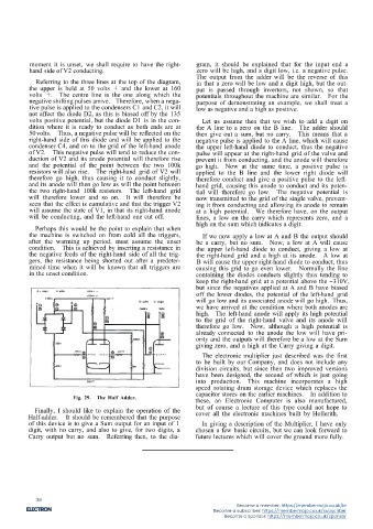
moment it is unset, we shall require to have the right-  gram, it should be explained that for the input end a
          hand side of V2 conducting.                           zero will be high, and a digit low, i.e. a negative pulse.
                                                                The output from the adder will be the reverse of this
            Referring to the three lines at the top of the diagram,  in that a zero will be low and a digit high, but the out-
          the upper is held at 50 volts + and the lower at 160  put is passed through invertors, not shown, so that
          volts +.  The centre line is the one along which the  potentials throughout the machine are similar.  For the
          negative shifting pulses arrive. Therefore, when a nega-  purpose of demonstrating an example, we shall treat a
          tive pulse is applied to the condensers C1 and C2, it will  low as negative and a high as positive.
          not affect the diode D2, as this is biased off by the 135
          volts positive potential, but the diode D1 is in the con-  Let us assume then that we wish to add a digit on
          dition where it is ready to conduct as both ends are at  the A line to a zero on the B line.  The adder should
          50volts.  Thus, a negative pulse will be reflected on the  then give out a sum, but no carry.  This means that a
          right-hand side of this diode and will be applied to the  negative pulse is applied to the A line, which will cause
          condenser C4, and on to the grid of the left-hand anode  the upper left-hand diode to conduct, thus the negative
          of V2.  This negative pulse will tend to reduce the con-  pulse will appear at the right-hand grid of the valve and
          duction of V2 and its anode potential will therefore rise  prevent it from conducting, and the anode will therefore
          and the potential of the point between the two 100k  go high.  Now at the same time, a positive pulse is
          resistors will also rise.  The right-hand grid of V2 will  applied to the B line and the lower right diode will
          therefore go high, thus causing it to conduct slightly,  therefore conduct and give a positive pulse to the left-
          and its anode will then go low as will the point between  hand grid, causing this anode to conduct and its poten-
          the two right-hand 100k resistors.  The left-hand grid  tial will therefore go low.  The negative potential is
          will therefore lower and so on.  It will therefore be  now transmitted to the grid of the single valve, prevent-
          seen that the effect is cumulative and that the trigger V2  ing it from conducting and allowing its anode to remain
          will assume the state of V1, in that its right-hand anode  at a high potential.  We therefore have, on the output
          will be conducting, and the left-hand one cut off.    lines, a low on the carry which represents zero, and a
            Perhaps this would be the point to explain that when  high on the sum which indicates a digit.
          the machine is switched on from cold all the triggers,  If we now apply a low at A and B the output should
          after the warming up period, must assume the unset    be a carry, but no sum.  Now, a low at A will cause
          condition. This is achieved by inserting a resistance in  the upper left-hand diode to conduct, giving a low at
          the negative feeds of the right-hand side of all the trig-  the right-hand grid and a high at its anode.  A low at
          gers, the resistance being shorted out after a predeter-  B will cause the upper right-hand diode to conduct, thus
          mined time when it will be known that all triggers are  causing this grid to go even lower.  Normally the line
          in the unset condition.                               containing the diodes conducts slightly thus tending to
                                                                keep the right-hand grid at a potential above the -310V,
                                                                but since the negatives applied at A and B have biased
                                                                off the lower diodes, the potential of the left-hand grid
                                                                will go low and its associated anode will go high. Thus,
                                                                we have arrived at the condition where both anodes are
                                                                high. The left-hand anode will apply its high potential
                                                                to the grid of the right-hand valve and its anode will
                                                                therefore go low.  Now, although a high potential is
                                                                already connected to the anode the low will have pri-
                                                                ority and the outputs will therefore be a low at the Sum
                                                               giving zero, and a high at the Carry giving a digit.
                                                                 The electronic multiplier just described was the first
                                                                to be built by our Company, and does not include any
                                                               division circuits, but since then two improved versions
                                                                have been designed, the second of which is just going
                                                               into production.  This machine incorporates a high
                                                               speed rotating drum storage device which replaces the
                                                               capacitor stores on the earlier machines.  In addition to
                        Fig. 29.  The Half Adder.
                                                               these, an Electronic Computer is also manufactured,
            Finally, I should like to explain the operation of the  but of course a lecture of this type could not hope to
                                                               cover all the electronic machines built by Hollerith.
          Half-adder.  It should be remembered that the purpose
          of this device is to give a Sum output for an input of 1  In giving a description of the Multiplier, I have only
          digit, with no carry, and also to give, for two digits, a  chosen a few basic circuits, but we can look forward to
          Carry output but no sum.  Referring then, to the dia-  future lectures which will cover the ground more fully.


                                                            21


             38
                                                                             Become a member: https://membermojo.co.uk/ie
                                                                     Become a subscriber: https://membermojo.co.uk/subscriber
                                                                         Become a sponsor: https://membermojo.co.uk/sponsor

