


Page 32 - Autumn 2024
P. 32
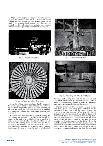
When a print magnet is energised its armature de- Before the machine was converted to electronic oper-
presses the marking wire on to a typewriter ribbon ation its speed was 10 cards per minute. This has now
causing its cross section to make an impression on the been increased to 20 cards per minute. A number of
card. A predetermined pattern can therefore be other advantages are also obtained but time does not
printed on the card, above any column, by operating permit a full explanation.
simultaneously a particular combination of magnets.
This concludes the description of this machine and,
although not by any means complete, gives an idea of
its capabilities.
THE ELECTRONIC MULTIPLIER
Now in the two machines already described the influ-
ence of electronics on the first was not to increase its
speed but to improve its operation, whilst in the case of
the interpreter electronics has doubled its speed, in
Fig. 13. Card Movement Control. addition to improving its operation. It will be noted
that both machines have remained basically the same,
thus extinguishes it. When the previously mentioned the only alteration made to the interpreter was to re-
cam again makes contact the first valve will again fire place high speed relays with thyratrons. But when we
and the second will be extinguished by the condenser come to consider electronic calculators, and to compare
and this procedure continues until the end of the card them with their electro-mechanical counterparts, the
when all 80 columns will have been interpreted. increase in speed is almost unbelievable.
Fig. 9. Print Head and Base Fig. 11. The Print Head Wires.
It is interesting to note that the printing takes place Take, for example, the speed of the relay operated
during the 5 millisecond delay before rack movement. multiplier, dealing with sterling amounts. This machine
could deal with 700 cards per hour, for an 8 digit
When the card is not punched in certain columns the multiplier giving a 16 digit product, but the electronic
machine can be made to skip these quickly by plugging multiplier can deal with 6,000 cards per hour for a 9
the control panel. digit multiplier and a 14 digit multiplicand giving a 23
digit product.
It should be stressed here that the speed given for the
electro-mechanical multiplier is the minimum speed,
and that it could, of course, be increased if the number
of digits in the multiplier or multiplicand were reduced.
The speed for the electronic multiplier is constant,
irrespective of the job in hand.
In order to achieve this increase in speed, it was
necessary to use another system of notation. The idea
of using the normal 0 to 9 as used in conventional
arithmetic, as on electro-mechanical multipliers, has
been dropped and in its place the Binary system is used.
Fig. 12. The "Dog In" "Dog Out" Magnets,
the rack, and to stop the card the latch is returned. Pig. 14. The Skip Control.
Fig. 10. A "close up" of the Print Head. This latch is controlled by two electro magnets, one to The skipping is arranged by means of the thyratron
The mag-
cause it to lift out and the other to return it.
It may be of interest to note here, that by means of nets are in turn controlled by two thyratrons. V3. The 2nd grid of V2 is normally held at +30V,
the control panel fitted to the machine, any letter or thus allowing it to conduct when its control grid is made
figure can be programme printed, without punching on The first thyratron is fired via a cam-operated contact positive. But the 2nd grid of V2 is connected to the
the card, and that if the card does happen to be punched and relay point. The relay point indicates to the anode of V3 and when this valve fires its anode voltage
in a particular column the programme printing will machine that the card is in the correct position for drops from 110V to approximately l0V, thus causing
suppress it. printing on the first column. When this valve fires it the potential at the grid of V2 to go negative and pre-
energises the latch-out magnet and after a delay of 5
A word is now due about the method of feeding the milliseconds (due to the inertia of the moving parts) venting it from conducting. This means that the latch
card through the machine. The card is taken from the the rack begins to move. The action of the first valve is unable to mesh with the rack and the rack therefore
bottom of the pack by a feed knife driven by an electric firing causes the second valve to fire, and this valve travels out carrying the card with it.
motor and then collected by a mechanism which, under operates the latch-in magnet but the latch will not be The machine can be made to stop skipping by con- Fig. 15. Description of Binary "Introduction."
the action of a spring, takes the card through the re- pulled in until the first valve has been extinguished. A necting the anode of V3 to earth through a condenser
mainder of the machine, but is restrained by a latch condenser is connected across the anodes of the valves and the discharge from this condenser causes V3 to Before beginning a description of the principles and
type mechanism catching on a toothed rack. There- which, when the second valve fires, causes a reverse extinguish; this can be carried out from control panel operation of the electronic multiplier, an explanation of
fore to cause the card to move the latch is lifted out of polarity to be connected across the first thyratron and plugging. the Binary system of notation, which bears a relation-
15 16
32
Become a member: https://membermojo.co.uk/ie
Become a subscriber: https://membermojo.co.uk/subscriber
Become a sponsor: https://membermojo.co.uk/sponsor

