Page 30 - Autumn 2024
P. 30

this of course could not be tolerated in a machine              portion in the centre contains the printing mechanism,
                                                                 which is expected to run continuously throughout the            from which the cards are ejected into a container at the
                                                                 working day.  It was therefore decided to fit a thyra-          left of the machine.
                                                                 tron in the circuit.
                                                                   The hole in the card is sensed at the card brush, and
                                                                 causes a positive potential to be applied to the grid, the
                                                                 valve now fires and discharges the 2 µF condenser
                                                                 through the sorting magnet via the closed relay points,
                                                                 the valve extinguishes when the condenser discharges.
                                                                 The condenser is then recharged, before the next hole is
                                                                 read, by means of the Condenser Charge Cam.
                                                                   This arrangement has proved entirely satisfactory and
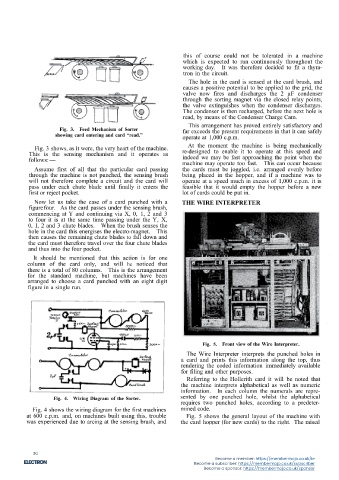
                      Fig. 3.  Feed Mechanism of Sorter          far exceeds the present requirements in that it can safely
                    showing card entering and card “read.”       operate at 1,000 c.p.m.                                                                                                           Fig. 8.  Printing Thyratrons.

             Fig. 3 shows, as it were, the very heart of the machine.  At the moment the machine is being mechanically
           This is the sensing mechanism and it operates as      re-designed to enable it to operate at this speed and
           follows:-                                             indeed we may be fast approaching the point when the
                                                                                              This can occur because
                                                                 machine may operate too fast.
             Assume first of all that the particular card passing  the cards must be joggled, i.e. arranged evenly before
           through the machine is not punched, the sensing brush  being placed in the hopper, and if a machine was to                                                                 the charactor control thyratrons will therefore require
           will not therefore complete a circuit and the card will  operate at a speed much in excess of 1,000 c.p.m. it is                                                           to be specially conditioned. The two grids of the valves
           pass under each chute blade until finally it enters the  feasible that it would empty the hopper before a new                                                              (2D21s) are used, one of these, of each of the 3, E, R
           first or reject pocket.                               lot of cards could be put in.                                                                                        and + thyratrons, is connected directly to the output of
                                                                                                                                          Fig. 6.  Rear view of Wire Interpreter.
             Now let us take the case of a card punched with a   THE WIRE INTERPRETER                                                                                                 the Card Read Thyratron which, it may be remembered,
           figurefour. As the card passes under the sensing brush,                                                                 The card is fed into the machine face upwards and  will cause the grid to go positive when a 3 is sensed at
           commencing at Y and continuing via X, 0, 1, 2 and 3                                                                   the punched holes are sensed by twelve brushes placed  the card reading brush.  The other grids of the valves
           to four it is at the same time passing under the Y, X,                                                                in the base of the machine.  The brushes are connected  are under the control of sign inverters.  It should of
           0, I, 2 and 3 chute blades.  When the brush senses the                                                                to earth and when a hole is sensed this connects the grid  course be remembered that both grids of the valve must
           hole in the card this energises the electro-magnet.  This                                                             of the associated Card Read thyratron to "carth" and  be at a positive potentia1 before it will fire.
           then causes the remaining chute blades to fall down and                                                               causes it to fire; the grids are normally held at 100V  Consider a card punched with a 3 only, we must then
           the card must therefore travel over the four chute blades                                                             negative.                                            suppress everything else except the 3 and this is achieved
           and thus into the four pocket.                                                                                                                                             as follows:-
             It should be mentioned that this action is for one                                                                                                                           The 2nd grid of the E valve is connected to the X
           column of the card only, and will he noticed that                                                                                                                                  Card Read Output.
           there is a total of 80 columns.  This is the arrangement                                                                                                                       The 2nd grid of the R valve is connected to the Y
           for the standard machine, but machines have been                                                                                                                                   Card Read Output.
           arranged to choose a card punched with an eight digit                                                                                                                      Thus neither of these valves will fire since the 2nd grid
           figure in a single run.                                                                                                                                                    will always be maintained at 100V negative.
                                                                                                                                                                                        The 2nd grid of the + valve is maintained at 80V
                                                                                                                                                                                      negative and is connected to the output of a cathode
                                                                                                                                                                                      follower which is only fired when a 0 is sensed at the
                                                                                                                                                                                      card brushes.
                                                                                                                                                                                        The 2nd grid of the 3 valve is connected to a sign
                                                                                                                                                                                      invertor and held at a positive potential, but the invertor
                                                                                                                                                                                      will cause this to go negative if either an X, Y or an
                                                                                                                                                                                      0 is sensed.
                                                                        Fig. 5.  Front view of the Wire Interpreter.                                                                    We now have the condition that one of the grids of
                                                                                                                                             Fig. 7. Card Read Thyratrons.            the R, E and + valves is held negative, thus suppressing
                                                                   The Wire Interpreter interprets the punched holes in
                                                                 a card and prints this information along the top, thus                                                               these thyratrons, whilst both grids of the 3 valve are
                                                                                                                                                                                                                      The output of this
                                                                                                                                                                                      positive and it will therefore fire.
                                                                 rendering the coded information immediately available           These thyratrons are used as cathode-followers and their
                                                                 for filing and other purposes.                                  outputs (negative going positive) are taken to the grids  valve is connected via rectifiers to the appropriate. mag-
                                                                                                                                                                                      nets of the print mechanism thus causing it to print the
                                                                                                                                 of sign inverters and the character control thyratrons.
                                                                   Referring to the Hollerith card it will be noted that                                                              figure 3.
                                                                 the machine interprets alphabetical as well as numeric            There are 40 character control valves, the outputs   A close examination of the Hollerith Card will reveal
                                                                information.  In each column the numerals are repre-             from which print the 26 letters of the alphabet, the  that the letters and figures printed along the top are
                    Fig. 4.  Wiring Diagram of the Sorter.      sented by one punched hole, whilst the alphabetical              figures 1 to 12 representing months and, in addition, two  composed of dots arranged in the correct order.  This
                                                                requires two punched holes, according to a predeter-             further valves for pence, i.e. 10d. and 11d.         is achieved by means of 35 wires arranged in 5 rows
            Fig. 4 shows the wiring diagram for the first machines  mined code.                                                    If we take for example the figure three it will be  of seven and connected at one end to a print magnet
          at 600 c.p.m. and, on machines built using this, trouble  Fig. 5 shows the general layout of the machine with          found to appear in the following combinations:-      armature.
          was experienced due to arcing at the sensing brush, and  the card hopper (for new cards) to the right. The raised
                                                                                                                                                                                   14
                                                             13


             30
                                                                             Become a member: https://membermojo.co.uk/ie
                                                                     Become a subscriber: https://membermojo.co.uk/subscriber
                                                                         Become a sponsor: https://membermojo.co.uk/sponsor
   25   26   27   28   29   30   31   32   33   34   35