


Page 41 - Spring Summer 2026
P. 41
Institution of Electronics News                                    Institution of Electronics News


 (c)  An  Electronic  Unit.  This  is  usually mounted
 remote from  the  point  of measurement and  its
 purpose is  to  convert  the  detector  output into a
 useful  electrical  signal  for  indication  or control.
 In the case of Geiger Muller Tube detectors, the
 Electronic Unit comprises  a  Pulse  Ratemeter,
 whose  d.c.  output can be  displayed  on  a  meter
 or recorder, can be used to operate relays, or can
 be fed into a proportional controller.
 ON/OFF CONTROL

 Fig. 2.  Gamma Ray Source Holders for level
 detection systems.
 a  range of source  holders  which  can be  used  with this
 type of detector.  The detector can be built in weather-
 proof or  certified  flameproof  form  and  contains,  in
 addition to the Geiger Muller Tube, a simple Ratemeter
 circuit and control  relay.  The trip level can be set for
 operation  at  any intensity  between  20  pulses/second
 and 200 pulses/second.  The  response time constant  of
 the circuit  is normally  8  seconds but  can  be  adjusted
 from about 1 second upwards.


 Fig.  1  (a).  A  simple  Level  Detector  employing a
 Geiger-Müller  Tube.  (Weatherproof version).


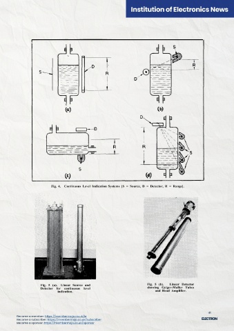
                           Fig. 4.  Continuous Level Indication Systems  [S  =  Source, D  =  Detector, R  =  Range].


 Fig. 3.  On/Off Level Detector mounted on a Sand Hopper.
 Detectors  of this  sort have  been installed on hoppers
 of sand,  coke,  lime,  wood-chips,  etc.,  storage tanks for
 latex, acids, etc.,  catalyst vessels, plastics coating plant,
 etc.  Fig. 3 shows a typical high level alarm installation
 on a hopper.
 Fig. 1  (b).  Flameproof Level  Detector.
 Owing to  the physical size  of  the  components,  and   CONTINUOUS LEVEL INDICATION
 the way in which gamma-rays are absorbed, the method   Owing to the  physical size  of  the  components  and
 is  particularly suited  to  two-step  or On/Off  operation   the  way  in  which  the  gamma-rays  are absorbed,  con-
 at a fixed level.  For this purpose it is simply necessary   tinuous  level  indication  is  generally limited  to  small
 to  mount a  "point"  source and  detector  on opposite   ranges up to, say, 2 or 3 feet, and above this range the
 sides of the vessel at the critical level.  The change in   system  becomes  cumbersome  or completely  impractic-
 signal intensity as the contents fall  below or rise above   able, depending  on the  type  of  vessel.  Fig.  4 shows
 this level  is usually  more  than sufficient  for  reliable   schemes which can be used for continuous level indica-
 operation of a control relay.  Thus, the trip level of the   tion over a moderate range.
 relay can be  set  without further  need for  adjustment   Method  (a)  uses  a  linear source  and  linear detector
 over  the  period  of one  source  half-life. Recalibration   and  this can  be  made  to  operate  extremely  well  over
 is not  required  and no  access to  the  contents  is neces-   ranges  of up to 2 feet,  provided  that the vessel dimen-
 sary in  order to determine the level at which control is   sions  are not  too  large.  The response  can  be made
 taking place.  Generally,  accuracy  within  ±  ¼ inch  is   linear in  most applications.  This  type  of  installation
 easily achieved.  Fig.  1  shows  a typical self-contained   has  been  provided  for certain  types  of Catalyst Towers   Fig.  5  (a).  Linear Source  and   Fig. 5  (b).   Linear  Detector
 detection system  for  On/Off  control and  Fig.  2  shows   and Storage Tanks for corrosive liquids.   Detector for  continuous  level   showing Geiger-Muller  Tubes
                              indication.                                       and Head  Amplifier.
 31                                                         32


 40                                                                                                        41
 Become a member: https://membermojo.co.uk/ie  Become a member: https://membermojo.co.uk/ie
 Become a subscriber: https://membermojo.co.uk/subscriber  Become a subscriber: https://membermojo.co.uk/subscriber
 Become a sponsor: https://membermojo.co.uk/sponsor  Become a sponsor: https://membermojo.co.uk/sponsor

